Introduction
One of the most eye-opening courses I took in college was an introduction to control theory course. The topic was brand new to me. Prior to taking the course, I had never even heard of this concept of “control theory”.
The course provided a brand new level of abstraction for thinking about how software fits in with the rest of the world. It provided the tools and vision for creating software and physical devices in harmony, to produce desireable, accurate, repeatable actions.
Software and physical devices in harmony
Sounds sorta familiar, huh?
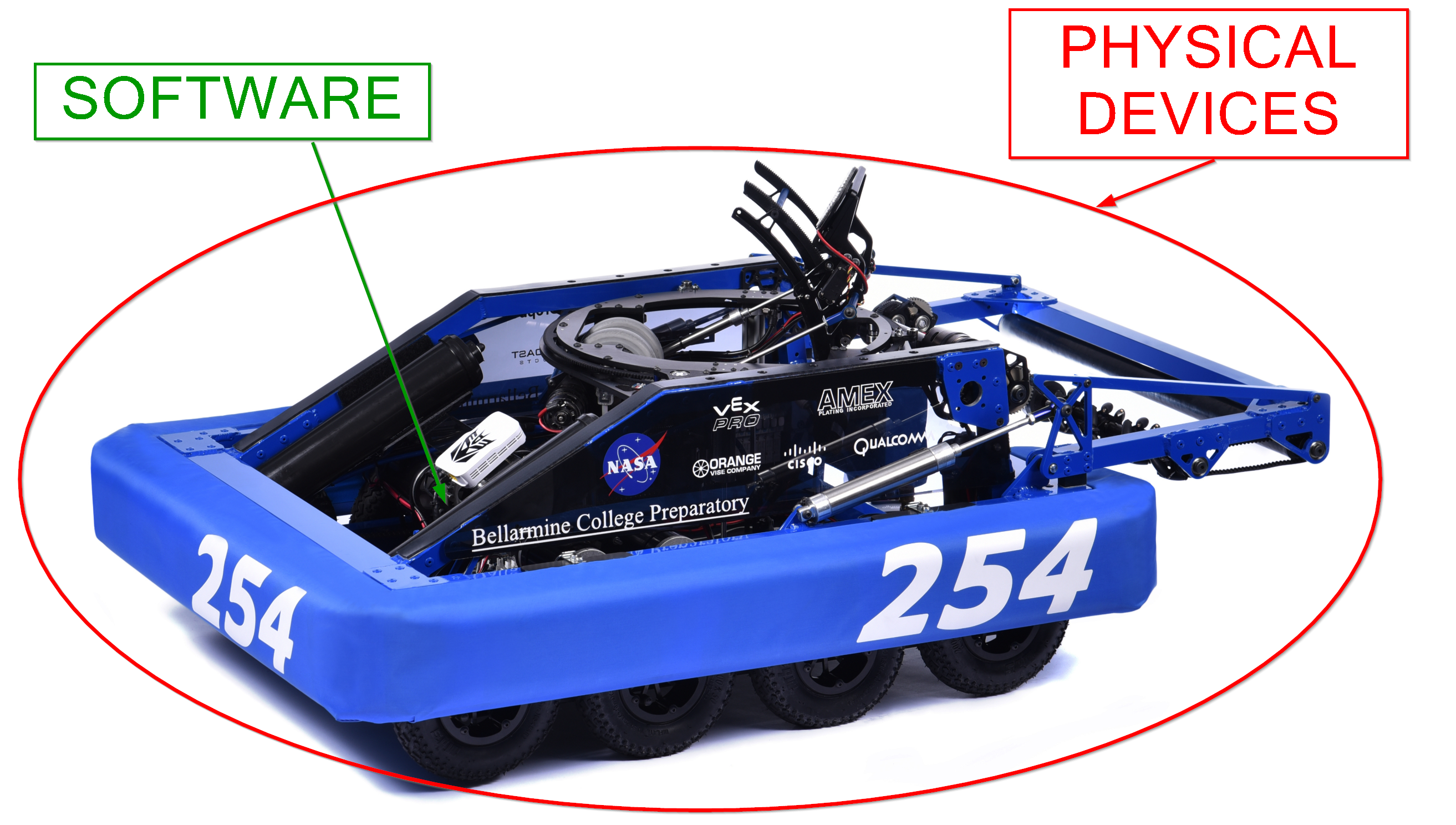
Source: team254.com
I did a couple cool projects in the class, but largely didn’t touch the subject much academically. But boy, did it influence the way that I approach problem solving. And it has been the single greatest driving force in my design philosophy for robotics - both in college, and into FRC mentoring.
I want to start a series of posts on the topic. We’ll start by talking more about the formal definitions of “System” and “Controls”, dig into a bit of the math (with lots of pictures, don’t worry), and finally talk a bit about controller design - leading into the mysterious land of PID.
If you’ve spent any time around robotics, you’ve most certainly heard the term PID - this mystical thing that you put in code, and then it magically solves problems! Right?
Eeeh, not so much. It can solve certain problems, but only under certain constraints. The study of Control Theory will give us the answers on which problems and which constraints.
The ultimate goal? Make mechanical systems do our bidding. Nothing more, nothing less. Let’s dive in!
Defining a System
A Control System, or simply a System, is a carefully-selected collection of mechanical parts, electronics, and software. Additionally, these pieces interact with each other. That’s it. Its super vague by itself. The academic treatment is purposefully vague, so as to explore the surprising similarities between seemingly disparate situations.
Usually, a control system in robotics consists of the following components:
- An Input Command, which describes what the mechanism should be doing.
- This could be from a human operator’s gamepad, or maybe an autonomous routine.
- The Controller, a piece of software running on a processor which you can freely adjust
- This usually lives on the roboRIO, but the software itself can be written as you please.
- An Actuator, the set of electronics and motors and solenoids which exert a force on the mechanism
- FRC rules restrict your set of choices here, but still allow some freedom.
- The End Effector, the part of the mechanism you are attempting to move in some “desired” manner.
- This is usually the thing your mechanical team designs and builds. There is some potential to change it, but its design is often fixed.
- The Feedback Sensor, something which measures the mechanism, and provides information to the Controller.
- This can often be freely chosen, though due to mechanical constraints often has to be mounted in a certain location on the mechanism.
As you can probably see, every control system has some parts which you can freely design (like the software in the Controller), some components which you have much less control over (like the actuator, or the mechanism connecting the end effector. The goal is to use the components you can freely design to make the components you can’t freely design still do what you want.
Practical Example
As a concrete example, think about a shooter wheel from 2016 or 2017 games. In both games, a common design was to launch a ball by spinning a rubber wheel up to a certain speed, then injecting the ball into the spinning wheel. The common “controls” requirement (aka “desired” behavior) was to ensure the wheel had a particular speed prior to injecting the ball, in order to keep the trajectory consistent. Here’s a concrete example of components that could be used to build up such a system:
- The Input Command came from a button on an XBOX controller. Pressed and the command is something like 1000RPM, released and the command is 0 RPM.
- The Controller, as always, was some software on the roboRIO. We’ll delve into the design of this software later.
- The Actuator was some speed controller (like a Victor SP) wired to a motor (like a 775 Pro)
- The End Effector was some rotating, rubberized wheel. Usually, this was propelled by the actuator, via a gearbox.
- The Feedback Sensor was a quadrature encoder, splined to some rotating member in the motor/gearbox/launch wheel system.
Vocabulary
In more standard control system terminology, the following nomenclature is used:
- The value of the Input Command is called the Desired value.
- The value of the Feedback Sensor is called the Actual value.
- The software and computer and actuator electrical components are collectively called the Controller
- The mechanical portion of the actuator, the end effector, and the linkage between all this and the feedback sensor are collectively called the Plant
- The output of the controller, into the plant, is called the Control Effort
The Controller/Plant terminology dates back to when control systems were primarily for Chemical Engineering processes at chemical production plants - Engineers designed controllers to make their plants do what they wanted.
The Actual and Desired values must both describe the quantities associated with the end effector you are trying to control - its speed, its position, etc. In the case of the shooter wheel, it’s the rotational velocity of that launch wheel end effector.
The Controller’s job is actually fairly simple: Make the Actual value match the Desired value as closely as needed. That’s it! How this is accomplished is much more less simple, and is heavily dependant on the nature of the plant.
One additional note: The feedback sensor is technically optional, and is not present in some systems. We will discuss this in more detail later.
The Block Diagram
The core tool used while describing control systems is the block diagram. Teams who use Labview will already be well familiar with this concept. However, for the sake of the text-based language teams, let’s delve in a bit.
A block diagram uses labeled blocks to show entities, and arrows to show relationships between the entities.
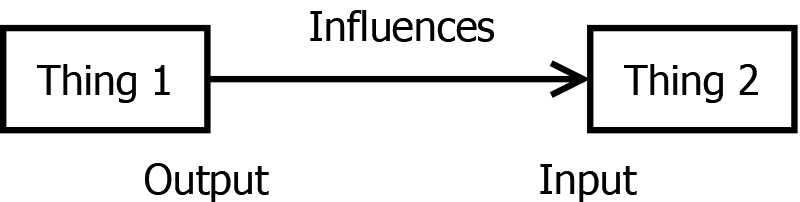
The blocks can be defined to be anything you like - a controller, a plant, part of a plant, your dog, etc. You choose what to put inside the block, so as to communicate your intent most clearly. The block is an indication of an abstraction - it shows the functional part you want your reader to be thinking about. No additional, unimportant details.
As a silly example, let us explain a very critical concept for all FRC teams everywhere:
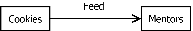
Here, we illustrate the concept of some sort of cookies providing sustenance to a group of mentors. It doesn’t matter what type of cookies, or how you made them, or what they cost. It doesn’t matter how the mentors eat the cookies, or how their bodies process the food, or whether you like the mentors or not. All these details are abstracted behind those nicely named little boxes.
Arrows indicate a quantitative relationship or flow of data from one block to another. Note we kinda violated that in our silly example. Maybe it’s “Calories”… doesn’t matter I suppose. It’s a silly example.
For real control system work, you’ll want your relationships to by quantifiable. That is to say, you can describe their value at any point in time using a number. It could be a command communicated to a motor controller, a force applied from one mechanism to another, a position detected by a sensor, an electrical signal generated by a sensor and sent to a controller… you get the picture. The key is quantitative - arrows are like assignment in variables, and actually get interpreted as such when you write software or do math based in block diagrams.
Note that we’ve provided a label over the arrow for clarity. This sometimes is useful, but also may be omitted in two cases:
- The relationship is obvious, such that the label crowds the diagram without adding additional information.
- The relationship is purposefully left vague, such that the diagram may apply to many scenarios at once.
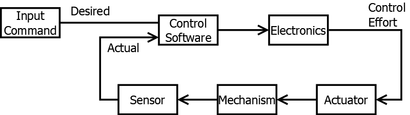
Now for a more serious example. In our standard construction of a control system, we usually can draw the following block diagram:
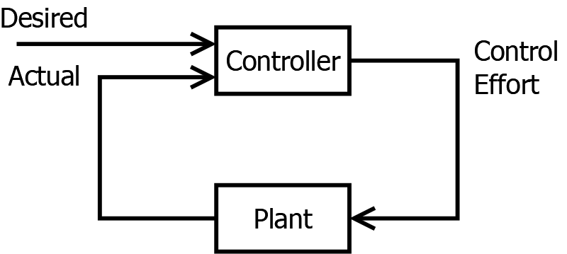
This illustrates the most basic breakdown of a system that control engineers will do. It illustrates the key concepts we’ve already discussed:
- Some outside entity provides a Desired value
- Something inside the Plant is measured, producing the Actual value
- The controller exerts a Control Effort onto the Plant
Thought not a hard and fast rule, I will generally draw things you can freely design in the top row, and things you cannot freely design in the bottom row. Just a convention to help visually organize the parts of the problem.
Finally, if you ever hear about “Feedback” in a control system, you can take the words quite literally. As you can see in the bottom row, data is literally fed back from the controller, through the plant, and back into the controller. The data in the bottom row literally flows backward, visually, in the diagram.1
Often useful is a more detailed diagram, where we break up the Controller and Plant blocks into components that can be more easily mapped to real components on the robot.
Here, you should see that perform the following “un-abstractions” to give a more detailed and usable view of the world:
- We specify that our Controller shall be made up of software, plus some electronics to bring the software outputs to the physical world
- We specify that our Plant is made up of an electrically-powered actuator, some physical mechanism attached to that actuator, and a sensor measuring that mechanism.
This is probably the most common permutation seen in FRC robotics, but note it doesn’t have to always be this way. For example, your controller might contain zero electronics. Or, your plant might actually be the stock market. I say this more as an aside, just to show how broadly this Control Theory topic can be applied. However, for FRC purposes, we’ll focus on the software-electronics-hardware-sensor model.
To further drive home this process, let’s put some specific component labels down in this diagram for our example shooter system described earlier:
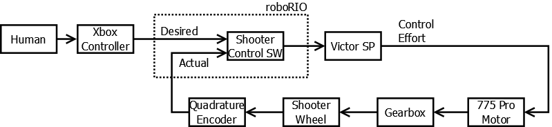
Here we see the mechanism further broken down into a gearbox and shooter wheel, and some specific component choices made to simplify explanation later on. Play along with us, and by the end you’ll be able to fill in the boxes for your own bespoke robot systems!
But, Why Feedback?
Earlier on, I mentioned that the sensor (and therefor, the whole Feedback system) was not technically required. Such a system is called “Open Loop”, as there is no information about the results of the control effort passed back into the controller. The loop of signal flow is left “open”.
This is, admittedly, a much simpler setup. No need to worry about feedback. It’s totally feasible too - as long as you know exactly how your plant will respond to each and every sequence of control effort inputs, you can 100% predict where your actuator will end up. If you just work this prediction math backward, you arrive at a solution for a control effort that puts your actuator exactly where you want it.
The key - plant models are usually unpredictable. Carpet has bumps. Battery voltage fluctuates. Parts expand and contract with temperature changes. Competition fields have slightly different dimensions than your practice field. Joe Freshman forgets to grease gears properly between matches. No matter how good at math you are, you can’t predict exactly how and when these will impact your system.
Whenever these disturbances are big enough to impact system function in a meaningful way, you need feedback and controller design that can deal for this variation, correcting for it.
Next Steps - Control System Design
Ok, we’re at a good point to take a quick step back, and look at where we are at.
The most general sequence of steps I can provide when it comes to problem solving are as follows:
- Describe the problem
- Design a solution
- Implement the solution
- Validate the solution works
So far, we’re partway through step 1. We’re building up a language and technique for describing the problem.
We’ve described how control systems are broken down into components, represented with nice little connected boxes. The next major task is to start to fill out the contents of each box.
For standard control theory design, each one will require a mathematical description - a model - of behavior. Fundamentally, each model will be description of how the input impacts the output.
Finally, we can apply control theory principles to design the mathematics of what we want the controller to look like, such that our actual value converges to the desired value in the most appropriate way.
So, next up, we’ll look at some examples of how to build up these mathematical models, and what important takeaways from the models we should expect.
After that, we’ll be able to move on to step 2, in which we design the contents of the Control Software box to make the whole system do what we want.
We’ll finish off with some thoughts on techniques for validating behavior on real hardware, and troubleshooting when it doesn’t work. Stay tuned!
Ready to keep going? Check out Mathematical Models!
Closing Note - On Other Resources
With any luck, I’ve at least peaked your interest in this topic. I do hope you will carry on in this sequence of posts. However, note, this will be an overview, with a focus on getting a ground up explanation of why certain FRC-relevant concepts work the way they do.
For a much more thorough and mathematically rigorous explanation of the topic, I HIGHLY recommend reading the textbook Controls Engineering in FRC - by far the best resource I’ve found on this topic. I’ll be making references to sections in this book throughout this series of posts. So far, we’ve discussed content from Chapter 1, Control System Basics.
-
Backward, assuming you read from left to right. Just the established convention. A convention which was clearly made by someone who didn’t read Hebrew. Sorry, Hebrew-reading friends. ↩