Calvin and Hobbes, by Bill Waterson
On Word Problems
As engineers, we almost always start with word problems. You know those paragraphs that your math teacher writes out that you have to read and then they make you extract the useful information to formulate some formulas, then solve them, then get the actual answer? Yea, those. I used to love those, because the paragraph-format meant the teacher couldn’t fit as many problems on one page, which meant shorter homework assignments!
Never in my professional life have I ever been asked “what’s ?”. Many times, I’ve had someone come to my desk and ask me a question that took ten sentences to explain, but at the end of the day all I had to do was calculate . That and listen to them, which is a whole skill (nay, art?) unto itself.
In previous posts, we’ve seen how logic gates can be combined to manipulate bits. There’s obviously a ton of different ways you could combine a set of bits… OR’ing them together, AND’ing them together, some combination of the two… But, why would you do such things?
Word problems. Every engineering problem starts as a word problem. So to learn about digital devices, we’re going to frame a couple word problems. Some of them may seem a bit odd at first, but I promise they’re building up to something very useful. Keep in mind, we’re laying the foundation for understanding the guts of a computer, which is going to help us write better software.
Rocket Launch Controller
Well, a contrived one at least. Part of one, not the whole thing.
Let’s imagine a usual rocket launch. We’re sending some people into space atop a very very powerful flaming pushy thing. You want to be sure everyone is OK with going to space before you actually try to go to space.
Mission control is keeping track of the launch, and has the responsibility of initiating it. Maybe we could give them one big launch button. But, this could be problematic - what if someone trips and falls and lands on the button? Then our rocket gets launched unexpectedly. This could be bad .
For safety’s sake, let’s build two buttons and put them on opposite sides of the room. The rocket shouldn’t launch unless two different launch control engineers push both the buttons at the same time. “Hey Bob, ya ready?” “Yea Joe, let’s light this candle!” “Ok, push the button” “Sounds good!” BWWWUWUSUSHSHSHSHSHSHSHSHHHHhhhhhhh……
But, we also have astronauts in the capsule. Mission control is pretty good at their jobs, but they aren’t at the rocket. Despite all their instruments, they still don’t hear, feel, or smell1 the behavior of the rocket. Maybe it’s wise to give our astronaut friends a “kill switch” of sorts inside the capsule. That way, if something seems off, they can activate some sort of “emergency stop” or “override” to prevent launch control from starting the rocket.
Buttons make great sources of boolean inputs. Though we won’t go into the details just yet, suffice to say that you have three boolean inputs, representing each of our three buttons. We’ll call the two in the launch control room and . We’ll call the “emergency-stop” button near the astronauts . For all buttons, a value of True indicates the button is pressed, and False indicates it’s not pressed.
We will have a single output called . When it’s True, it will trigger the ignitors to start the rocket, and send the thing to space. When False, the rocket remains on the launch pad.
How do we want to design this digital circuit to control the launch functionality as described? Let’s break it down into little chunks.
The launch room is kind of its own entity, with its own behavior, and own set of inputs. Let’s deal with that one first.
What is the information that comes out of the launch room that the rocket ignitors care about? I’d say that the information the rocket cares about is “Both buttons or pressed” - either they’re both pressed, or their not both pressed. Let’s call this intermediate value .
Looking inside the launch room, the logic should be pretty simple. Two inputs, one output. Let’s enumerate what we want to happen for each input:
| 0 | 0 | 0 | No button is pressed. Don’t Launch. | |
| 0 | 1 | 0 | Only one button is pressed. Don’t Launch Yet. | |
| 1 | 0 | 0 | Only one button is pressed. Don’t Launch Yet. | |
| 1 | 1 | 1 | Both buttons are pressed. Go for Launch! |
Astute readers will notice that this actually is a very familiar function - it’s just an AND gate!
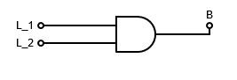
There we go, quite simple!
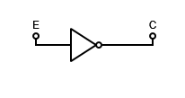
Now let’s move on to the astronauts. They’ve got one button that when pressed should indicate “inhibit launch”.
It’s generally a good idea to try to keep things as similar as possible. Since Launch Control has a single output that indicates “Go for Launch”, lets give our astronauts the same output. We need to design a circuit that takes their inhibit button value and converts it into a “Go for launch” output. We’ll call the astronaut output . Again enumerating with a truth table:
| 0 | 1 | Astronauts are not pushing their button. Everything must be ok, go for launch! | |
| 1 | 0 | Astronauts detected a problem and pushed their button! Don’t Launch! |
Astute readers will again notice this is actually a very familiar function - it’s just a NOT gate.
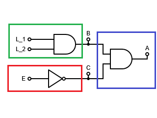
Excellent! We have now devices for both the Launch Control room and the Astronauts capsule controls, each with an output that says “Light the rocket” or “Don’t light the rocket”. The rocket ignition mechanism now has to take these two signals, and combine them together. Note from our initial requirement, we know we don’t want to launch the rocket unless both the astronauts and launch control decide it’s time to go.
| 0 | 0 | 0 | No one wants to launch the rocket. Don’t Launch. | |
| 0 | 1 | 0 | Astronauts say they’re ok to launch, but Launch Control doesn’t agree. Don’t Launch Yet. | |
| 1 | 0 | 0 | Launch Control wants to go, but astronauts saw a problem. Don’t Launch Yet. | |
| 1 | 1 | 1 | Astronauts say they are good to go, and Launch Control says good to go! Light the Rocket! |
Even the least astute of readers should be able to recognize this now. It’s another AND gate!
We can now put all 3 pieces of the puzzle together. Substituting equations:
In diagrams, we’d draw this as:
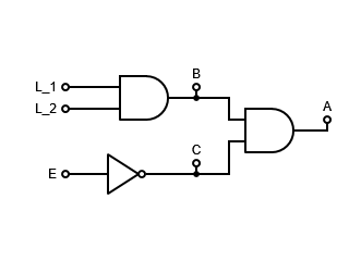
This simple logic diagram shows how we could implement logic to accomplish our basic launch control system.
Notes on Subdividing
Admittedly, this is a pretty simple system, and we took a very verbose and roundabout way to design it. I bet many of you saw the ending well before we got there. That’s perfectly fine! The big takeaway is not just the answer itself, but rather dividing the problem up into useful pieces. In this context, “useful” implies that each one is solvable on its own, and represents some meaningful small piece of computation. If you notice, you can easily draw boxes around the three physical locations we discussed:
The individual pieces may not be implemented by the same computer! You might have to have each piece on a different machine, since they’re in physically different places. This diagram and design doesn’t at all get into how one might transfer a boolean value from one place to another (radio? super long wire?), but for lots of purposes that doesn’t matter. Imagine your boss came up and asked “What does the system do”? They don’t care about the implementation details, they care about functionality. This would be a great diagram to show the high level behavior of the system, without getting bogged down on communication, button size, or other implementation details.
The wise engineer says to create designs (and present designs) at the easiest and most useful level of abstraction. The experienced and artful engineer can identify exactly what that level of abstraction is in their sleep.
Design Flaw
The critical student will have noticed that there may be a few gaps in our design.
One of them that I’ll address - the astronaut button. Let’s say that our friends detect a problem and want to prevent launch. With our current logic, if they tap their button, they’ll momentarily inhibit the launch, but as soon as they take their finger away the button springs back, allowing the launch again. It would stink to force them to have to hold down the button the whole time. We’d probably want to remember whether they’ve pressed it or not, and inhibit launch until someone corrects the issue that caused them to hit the inhibit button in the first place.
I can think of two ways to do this “remembering”. One is mechanically - don’t use a button, use something more like a light switch that doesn’t “spring-back” to the off position when you’re done. THe other is to remember the button press in software. This requires using memory, which is a concept we’ll cover later in this post.
Adders
We’re going to move on to a slightly more abstract, but much more realistic example.
Binary Addition
Recall from the binary lesson how we can add together base-2 numbers the same way we add together familiar base-10 numbers. The algorithm that I learned back in the day was:
- Line up the two numbers on top of each other, keeping each place vertically aligned.
- Starting from the one’s place, add together each single digit number
- If the result of a particular addition is 10 or greater, “overflow” or “carry” into the next column.
The exact same process works in binary. Recall:
Adding these two numbers in base-10, I get a result of 72. Let’s do it in binary, to show how a thing that only knows 1 and 0 might go about doing the same calculation:
First, we align the numbers:
Then, starting from the least significant bit, we start adding.
Note that (This is just , which you presumably learned in 1st grade.) Since the addition of two ’s has created a new digit, we have to carry it over to the next column:
Rinse-wash-repeat.
Therefor, we have to carry again.
We continue this process until we’ve covered all the bits in the number, and arrive at our result:
Huzzah! We have done the calculation using only 1’s and 0’s. Hey, digital logic uses only 1’s and 0’s. Do you think we could design some circuitry to do this? You bet your bottom dollar we can!
Patterns in Binary Addition
To build the logic, we’ll start by breaking down the problem. Look at a particular column of the above addition operation. Let’s try to describe its’ properties in general:
- It takes two bits as input, one each from the numbers we are trying to add.
- A third bit comes in from the previous step, to indicate whether the previous step resulted in a “carry” operation or not.
- It contributes one bit to the result number
- It also may pass a “carry” bit to the next step
As a bit of bookkeeping, let’s first write out a list of all the possible math facts we could need. Remembering that addition is associative:
Since we’re talking about only one stage, we’ll indicate which stage that is with an index subscript. The first stage will have subscript , the next subscript and so on. Some particular (but unspecified) stage - the “‘th stage” - will have subscript . As a matter of notation, when looking at the ‘th stage, the next stage will be , and the previous stage will be . We’ll have to explicitly handle the end-cases, but ignore them for now - just think about the middle bits.
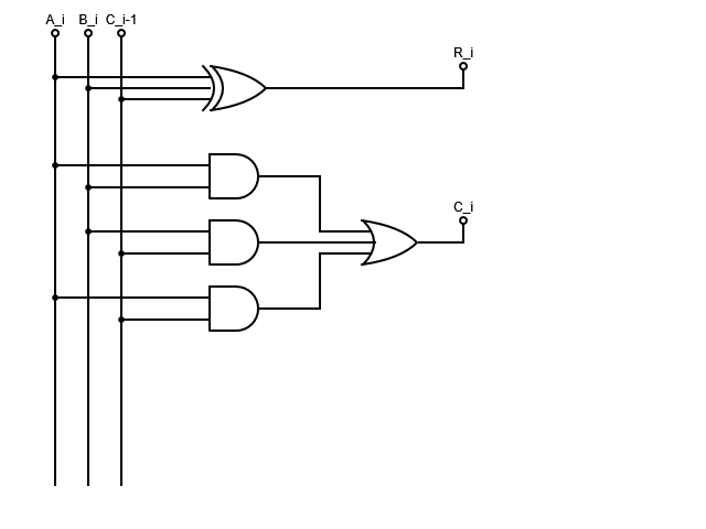
To draw this a bit more clearly, let’s cover all 3 inputs and both outputs in a table.
We’ll call the two bits to add and , and the result . Each stage will also output a Carry signal called . Since each stage also takes an input from the previous stage’s carry signal, we’ll denote this input with
| 0 | 0 | 0 | 0 | 0 | |
| 0 | 0 | 1 | 1 | 0 | |
| 0 | 1 | 0 | 1 | 0 | |
| 0 | 1 | 1 | 0 | 1 | |
| 1 | 0 | 0 | 1 | 0 | |
| 1 | 0 | 1 | 0 | 1 | |
| 1 | 1 | 0 | 0 | 1 | |
| 1 | 1 | 1 | 1 | 1 |
Single Bit Adder
A single bit adder will be a device with three inputs (the two bits to add, plus a carry-in bit). It is actually two independent circuits, outputting the Result bit and the Carry-out bit. We’ll design each one, one at a time.
Result Bit
If you stare at the truth table hard enough, you might notice that the result bit is 1 whenever the number of input signals is odd. There are more algorithmic methods you can use to determine this, but recognizing this pattern lets you make the quick shortcut. Recall from previous posts that an XOR gate outputs 1 when an odd number of its inputs are 1. So, we’ll use an XOR gate:
Carry Out Bit
The carry out bit also has a bit of a pattern to it. Notice that it is true when at least two inputs are true. This can be covered by a series of OR’ed together AND outputs as such:
Again there are algorithms you can use to derive this equation from the truth table, but if you stare at it hard enough, you should be able to convince yourself that this equation is both accurate, and makes sense. For example, think about why we don’t have to handle the all-three-inputs-true case explicitly.
Schematic
Based on our observation of the truth table, we can put together this device that can compute one column of the “add two bytes” problem:
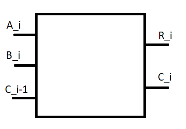
To use many of these devices in larger units, we’ll use an abstraction where we draw just the inputs and outputs, and hide the details of the guts.
Ripple-carry Adder
The Ripple-carry Adder is a logical next-step to expand the single-bit adder. Earlier in the post we showed the algorithm for doing binary addition. Since it’s a bunch of rinse-wash-repeat steps, it stands to reason that we could make one circuit to do each step, then replicate and string them together. That’s exactly what we’ve done with the single-bit adder - we’ve made one circuit that can perform one step of the addition. A Ripple-carry Adder is simply a set of single-bit adders chained together to do addition of a full byte.
Joining chunks together
The hookup is pretty much what you’d expect: Every bit in input bytes and is piped to the proper single-bit adder stage. The carry bits are passed from one layer to the next. The 0th carry-in bit is hardcoded to zero. The final output is an output of the Ripple-carry Adder, and can be used to know when the sum of the two numbers is outside the range of representable digits by that fixed number of single-bit adders.
For a 4-bit Ripple carry adder, the circuit diagram would look like this:
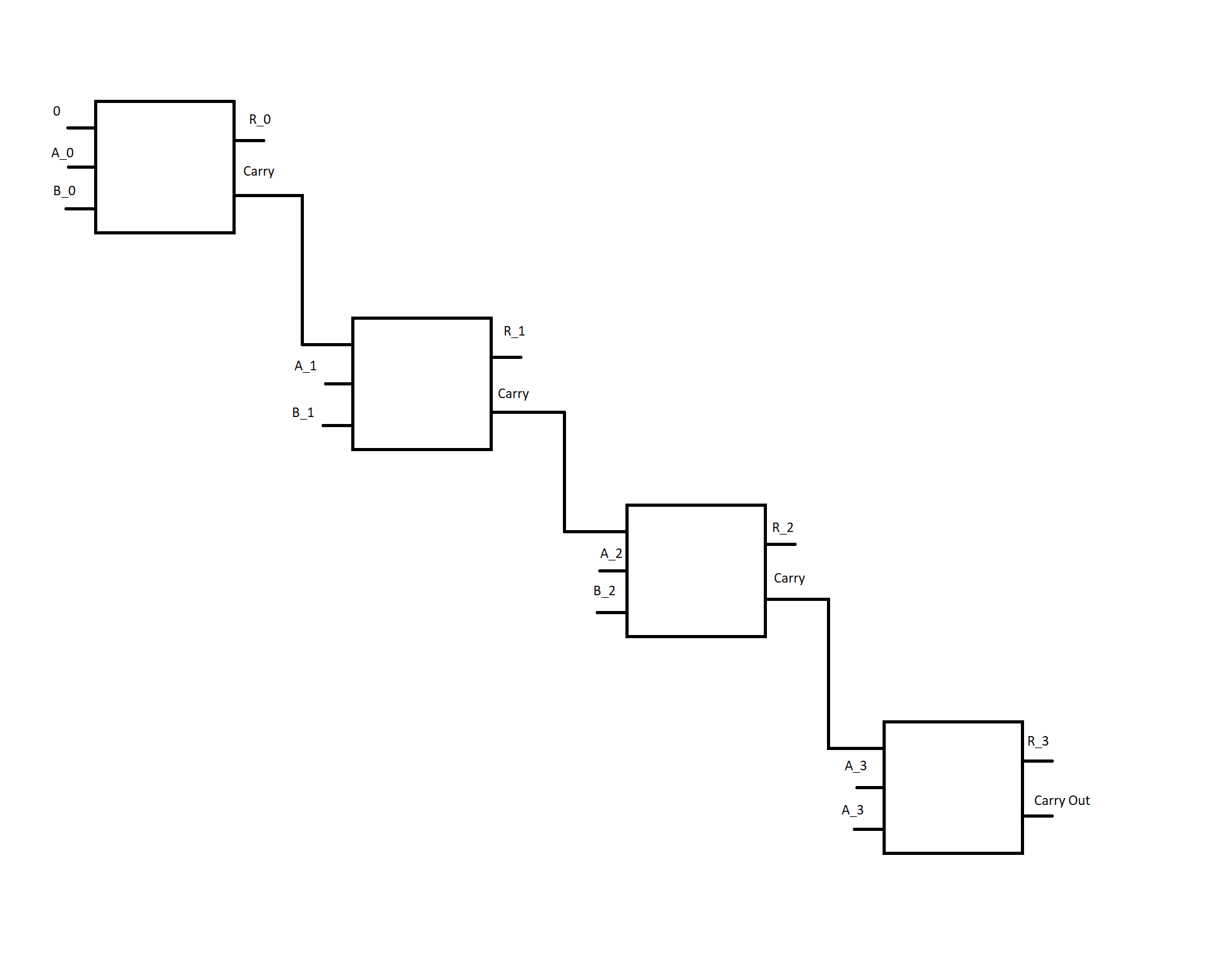
Notice how the “carry-out” from each stage ripples into the next stage. Hence the name. Someone was clever like that.
Hopefully you can see - if you need more bits (say, 8, or 64?), you just add more stages.
Next Steps - Where are we going?
We’ve discussed digital circuits which are capable of transforming inputs into outputs, but not yet discussed how to create circuits which can remember past events. This will be a critical step if we want to be able to store any data while running our computer programs. We’ll delve into this in Part 2!
-
Yes, smell. A good engineer uses most of their senses! Learn the smell of burning electronics, and learn to shut off the power as soon as you smell it! It’s a great way to identify the source of issues, and get early detection of a failure - you can often smell it before you see smoke. Of course, be careful not to inhale anything super toxic. For that same toxic ingestion reason, I don’t usually recommend the sense of taste for writing software. ↩