“All you need is NAND… ba da da da da” - Professor Michael Loui, 2010, UIUC
Combining Bits
In this post, we’ll start to dig into how you combine bits together. Previously we’ve looked at how to interpret, generate, and analyze sets of bits. Now we want to do operations on them. Just like how you add and subtract numbers, so to can 1’s and 0’s be combined and manipulated.
If you remember our friend Mr. Boole from previous posts, what we’re about to go through is a primer on the logical system he formulated.
Boolean Functions
Recall from the math primer how we looked at the concept of a function as an abstraction of mathematical behavior. Just like with normal base-10 numbers, functions can be defined for acting on boolean numbers too!
We often describe a boolean function with what’s called a truth table. Due to the discrete nature of only allowing each input to be True or False, it’s often easy to completely enumerate the set of all possible inputs to the function.
The functions we’ll concern ourselves with take inputs, and produce a single output.
If you recall some of the math we learned in previous posts, you could probably have guessed that a function with boolean inputs has possible input combinations, which means it has outputs to describe in a truth table. Of course, each of those outputs will be simply 1 or 0, but which ones are 1 and which ones are 0 is the question a truth table answers for you.
As a sample with , we will organize truth tables like this:
| In1 | In2 | In3 | Out | |
|---|---|---|---|---|
| 0 | 0 | 0 | 1 | |
| 0 | 0 | 1 | 1 | |
| 0 | 1 | 0 | 1 | |
| 0 | 1 | 1 | 1 | |
| 1 | 0 | 0 | 1 | |
| 1 | 0 | 1 | 1 | |
| 1 | 1 | 0 | 1 | |
| 1 | 1 | 1 | 1 |
All inputs come first, and the output is in the last column. This isn’t a particularly interesting function, as it always outputs the same thing, no matter what the input is. I like to call this function “a wire connected to +5V”.
Let’s dig a bit deeper into some interesting functions. They don’t call them functions for nothing.
Fundamental Logic Functions
Most of the basic boolean functions have particular names. There are 3 very basic ones that almost all lessons on boolean logic will start with: AND, OR, and NOT.
Whoever came up with the names deserves a snickers bar, because the names actually make a ton of sense.
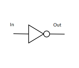
NOT
The simplest boolean function of interest to us has only inputs, which means there are two possible output states.
| In1 | Out | |
|---|---|---|
| 0 | 1 | |
| 1 | 0 |
As you can see, NOT performs an inversion of the boolean state. 1 is not 0, and 0 is not 1.
When you are writing an equation, you’ll generally use capital letters like or or or to indicate a variable which is boolean, and can take on 1 or 0 values.
For hopefully obvious reasons, the letters and are poor choices for boolean variable names.
If we assume that is our input, and is our output, we would denote the NOT function as the following:
This is to say that is the logical “NOT” of . Or, another way, to calculate , you invert .
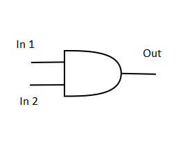
AND
AND is another fundamental function, but it takes two inputs, implying that there are four possible output states.
| In1 | In2 | Out | |
|---|---|---|---|
| 0 | 0 | 0 | |
| 0 | 1 | 0 | |
| 1 | 0 | 0 | |
| 1 | 1 | 1 |
As you can see, AND outputs a 1 if and only if both inputs are 1. In all other cases, the output is 0.
This is another great name for a function. The output is 1 if the first input is 1 and the second input is 1.
When you describe AND in an equation, you write it like multiplication. This means you might put a dot between the inputs, or maybe just write them next to each other. For example:
Both of these equations denote that is calculated as the logical AND of input variables and
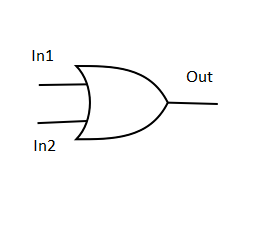
OR
OR is our last fundamental function. Like AND, it takes two inputs. Like AND, it is also fairly well named.
| In1 | In2 | Out | |
|---|---|---|---|
| 0 | 0 | 0 | |
| 0 | 1 | 1 | |
| 1 | 0 | 1 | |
| 1 | 1 | 1 |
You can see that OR outputs a 1 when either of its inputs is true - that is to say the output is 1 if the first input is 1, or the second input is 1.
Note that if both inputs are 1, the output remains 1 - this is a bit of a departure from how most folks interpret the word “or”. If your mom asked you “Do you want to go to Disney World or Universal Studios?” she probably wouldn’t be all that pleased if you said “Both!”. But ignoring this for now…
When you describe OR in an equation, you write it like addition. This means you have to use a plus symbol. For example:
This is the way to denote that is calculated as the logical OR of inputs and .
Equations, Order of Operations
As we’ve shown already, boolean operations can be indicated with equations, just like regular math. Similar to regular base-10 math, you use variables that take on the value of 1 or 0, constant 1’s and 0’s, equals signs, an order of operations (with parenthesis to change it)… most of what applies in normal math applies here too!
For example, take the following equation:
Let’s break this function named down into its components. Order of operations would dictate that you evaluate the inside of the parenthesis first. In this case, you first evaluate the OR of and .
The NOT bar is drawn over that whole quantity, so you calculate the NOT of the whole quantity . That is to say - you first calcualte OR , then invert the result.
Finally, is AND’ed with the result of that calculation. This produces the result .
In general, order of operations will be:
- Interior of Parenthesis
- NOT
- AND
- OR
Note that the NOT operation of putting a bar over a variable (or many) is kinda like parenthesis, where you are inverting a set of variables. Generally it’s better to be more verbose in calculations, and ask questions if the notation is unclear.
When writing these formulas down (on paper or in code), I always recommend to go whole hog on parenthesis. If there’s even a slight chance order of operation might be ambiguous, put them en. Even if this is redundant, it’s always better to ensure you communicate your intention to the reader, or the compiler.
Properties of Boolean Calculations
You may have heard certain terms from your math class like the “associative” property and the “communicative” property. I don’t like to get too stuck on terminology like this - it’s good to know it so you can communicate with others, but even more important you know the underlying concept. Suffice to say, for software writing’s sake, here’s a handful of useful ideas to keep in mind:
- The order of the inputs to AND and OR don’t matter. You can freely exchange inputs 1 and 2, and output is unchanged (inspect the truth tables, it’s easy to prove this by just looking at them). This can help you simplify calculations.
- Any quantity ANDed with 1 will be itself, and any quantity ORed with 0 will be itself
- This is often called the “identity” property. What it means is that if you see a or in an equation, you can trim it off without consequence. This is a useful fact when looking for ways to speed up a calculation.
- Any quantity ANDed with 0 will be 0, and any quantity ORed with 1 will be 1
- This is often called the “short circuit” property. What it means is that if you see a or , you don’t even have to bother doing the other half of the calculation, you already know the outcome. This is a very useful fact when looking for ways to speed up a calculation.
Gates & Drawing Diagrams
Written out equations are not the only way to represent a binary equation. Indeed, this particular form of math has become strongly oriented toward creating real-world circuits which do useful things. As a result of that, it is common to represent a boolean calculation using a schematic or diagram, indicating how one could potentially create hardware to perform the associated calculation.
Logic Gates
The diagrams that are drawn indicate how entities called logic gates will be hooked together to represent a whole circuit. A logic gate is an abstraction of the electrical circuitry (probably involving transistors) which could implement the logic function represented.
All of the fundamental operations we have mentioned so far have special symbols to indicate their identity.
NOT Gate Symbol
AND Gate Symbol
OR Gate Symbol
Logic Diagrams
When you combine multiple gates together, and hook them together in a particular way, you get what most folks will call a logic diagram describing your boolean function.
Take our previous simple example of a boolean function
Using our symbols, we can draw them together with function inputs and outputs, to graphically represent the same equation:
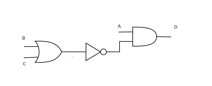
Note how information flows from left to right, just like you read. Your inputs are all on the left hand side, propagate through gates which transform and manipulate it, and eventually produce a single, final output on the right-hand side. This left-to-right flow convention is very commonly used in diagrams.
2-Level Logic
As it turns out, all boolean functions, no matter how complex, can be broken down into a two-level hierarchy. This can be either a set of AND calculations OR’ed together, or a set of OR calculations AND’ed together. You may have to invert some of the inputs with NOT operations, but otherwise, it’s just two levels of gates.
For software purposes, this is a useful fact to remember, but proving it is a bit more than what I’d want to get into in this post. Suffice to say, there are proofs that show arbitrarily large equations can be reduced into this manageable structure. Because of this, when analyzing or thinking about boolean logic, just keep in mind that two layers of gates is all that you will ever need.
Derived Gates
XOR
There is a somewhat common gate called the “Exclusive OR” that calculates the more traditional “This or That (but not both)” meaning of the word “or”:
| In1 | In2 | Out | |
|---|---|---|---|
| 0 | 0 | 0 | |
| 0 | 1 | 1 | |
| 1 | 0 | 1 | |
| 1 | 1 | 0 |
Another interpretation that’s often useful is that XOR outputs 1 when its inputs are different, but 0 when they are the same.
There is an equation symbol for it, but it’s not commonly used.
Indicates that C is the logical XOR of inputs A and B.
NAND, NOR
Finally, there are some additional gates which it’s good to be aware of:
NAND:
| In1 | In2 | Out | |
|---|---|---|---|
| 0 | 0 | 1 | |
| 0 | 1 | 1 | |
| 1 | 0 | 1 | |
| 1 | 1 | 0 |
NAND, or “Not AND” is just that - it’s an AND gate, but with the output inverted.
NOR
| In1 | In2 | Out | |
|---|---|---|---|
| 0 | 0 | 1 | |
| 0 | 1 | 0 | |
| 1 | 0 | 0 | |
| 1 | 1 | 0 |
NOR, or “Not OR” is just that - it’s an OR gate, but with the output inverted.
Symbols
Of course, there are symbols for these gates as well.
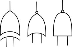
From left to right, they are XOR, NOR, and NAND. Outputs are at the top, inputs are at the bottom.
Note for NAND and NOR, the little circle on the output indicates the inversion operation. You may see that little circle elsewhere too - just know it implies “invert” on the signal it’s placed on.
Why NAND/NOR
As it turns out, when you go look at the transistor configurations required to create normal AND/OR gates, they’re actually NAND/NOR with an inverter on the output. In terms of design optimization, it actually is easier to design the logic in terms of NAND/NOR, because you will use fewer transistors in the final design. This makes for cheaper, simpler, and more energy-efficient designs - all around a good thing!
Even better - most modern electronics design tools can do the AND/OR to NAND/NOR transformation automatically for you, which means you can design in whatever set of gates is easiest for you to think about. Then the computer design tool can do the plug-and-chug to create a more efficient implementation.
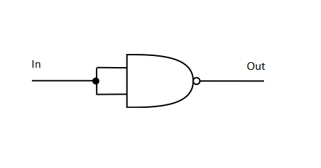
Furthermore, NAND and NOR have the interesting property of being able to emulate all the trivial gates themselves. Without a formal proof, and presented in pictures only, the evidence is presented below. Fun homework: Create a truth table for each of the below circuits to prove that they do in fact do what I claim they do.
NOT with NAND:
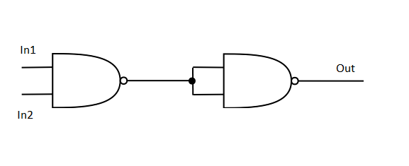
AND with NAND:
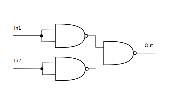
OR with NAND:
So what
Recall from further up that any boolean function can be represented Here’s the additional punchline, as Professor Loui sang to us in ECE 101 (to the tune of the Beatles “All You Need is Love”) - “All you need is NAND… ba da da da da”. Only having to have one gate around can also help simplify designs sometimes - whether that’s a software tool that’s trying to create the most optimum configuration of transistors for your design, or whether you just don’t want to buy 10 types of circuit chips from Digikey for your project…. having just one gate type is often not a bad thing. Huzzah for standardization!
Further Study in Boolean Logic
Proofs & Formal Math
If you spend some time looking through literature on this topic, you’ll find lots of formal proofs using axioms and things like “DeMorgan’s Law”. These are definitely good to take a peek through, but don’t have a ton of bearing on your ability to write good software. I’m also of the opinion that most of it is pretty self-evident if you stare at it long enough, to the point where it doesn’t make sense to do a formal introduction to them in this blog. As we get into discussing good coding techniques, these principles will naturally fall out.
Electronics
So, in case you were wondering, you can go out and buy logic gates! You will need to choose the right set of chips for the voltages you are using to represent 1 and 0. If you happen to go with the very-common answer of 5V = 1, 0V = 0, then Texas Instruments has for many many years made a beautiful line of “74- series” chips which robustly implement logic gates in a cute little DIP package. Lots of other manufacturers make pin-compatible versions of them. If you’re starting off, I recommend getting a “variety pack” with spares of each to enable experimentation and play.
Next Steps - Where are we going?
We’ve covered the basics of how bits can be combined and manipulated with fundamental logic gates. Moving forward, we’ll start to combine these gates into useful digital circuitry, building up to the main components of a computer processor. Go check out Digital Devices.
Alternately, we’ll also cover some of the practical implications when building digital circuitry in the real world. For Extra Credit, check out Electronics Part 2.